Click on this link for more photographs of my Audio Selection Panel..
WARNING: This page contains shockig images!
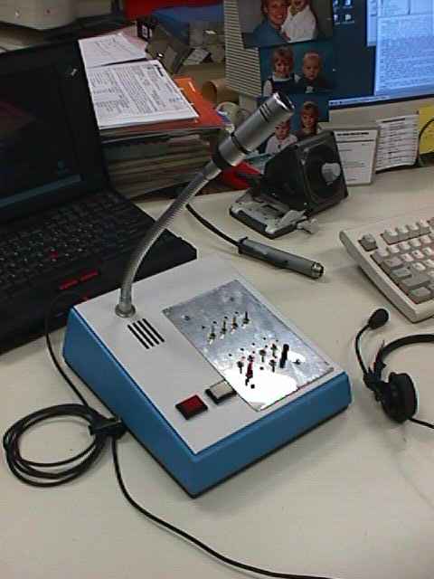
An Audio Selection panel in the shack
The design
On this page, you will find one of my designs; An Audio Selection Panel (ASP). The Audio Selection Panel allows you to control 4 Transceivers and hear the audio through the built-in loudspeaker and on an external boomset (combination Microphone/ headset). On or more transceivers can be selected at a time to transmit and/ or receive. An additional receptacle can be used to attach a recording device or the PC soundcard. There is no separation of signal ground between the connected transceivers. This does not cause any problems in my set-up (only VHF/UHF transceiver), but your mileage may vary.
Like most of my circuits, this one is built on experimental "vero-board" and I have no intention of designing a Printed Circuit Board. I built this design with 4 channels, but you may use any number of channels, depending on your needs. The housing is that of a commercial desktop microphone, bought cheaply in the Dutch radio amateur museum ‘ Jan Corver’ in Budel. All connectors (Power supply, audio for 4 transceivers, boomset and the PC soundcard), are mounted on the rear panel of the desktop microphone. Audio and PTT signals are combined in 9 pin sub-D connectors to reduce costs. The boomset and power supply use standard connectors, but you are free to choose your own! The design is split into a number of separate function blocks, each built on a separate piece of circuit board..
Pinout of the connectors I used.
The PTT circuit
The PTT circuit must deliver an active low (GND) signal to each individual transceiver. The PTT signal must be selectable for each individual transceiver and the transceiver may not influence each other. .A red LED indicates the PTT status per transceiver. Transmitting can be from either one of the two PTT switches on the front of the housing (one momentary, one hold), the PC RS-232 port or the boomset.
This is the circuit for the PTT signal:
Diodes D1..D4 isolate the PTT signals between the transceivers. Switches S6 (PTT Hold) en S5 (PTT Moment) are mounted on the front panel, as are switches S1..S4. S1..S4 are used to select one or more transceivers te transmit as switches S5, S6 or the boomset PTT button are pushed. The red LEDs D1..D4 (Tx1..Tx4) display PTT status per transceiver and are mounted just above S1..S4. Boomset PTT and Computer PTT (from the RS-232 port) are buffered by a Reed relay. All diodes are 1N4001 (General Porpose 1 Amp Silicon)
Microphone amplifier/ clipper
The maicrophone works according to a ‘hot mike’ principle; the amplified microphone signal is routed continuously to all 4 transceivers and the boomset speaker amplifier (as a ‘side-tone’). A Switch (S7) selects either the tablemicrophone or the boomset microphone as active. My boomset has a built-in (19dB) amplifier and needs DC power on the signal lead. It may be necessary to adapt the circuit to the microphones you use, byadding an additional signal amplifier, or deleting the DC power on the microphone signal wire.
The table microphone has a balanced microphone element inside. This balanced signal is buffered and amplified by a separate OPAMP. Two 1n5 Caps on the microphone signal lead were added to prevent a humming interference tone when transmitting on VHF/UHF. Without this circuit, the table (goose-neck) microphone was sensitive to external electric fields, resulting in 100Hz interference when apprached by my hand..
The signal from the first microphone amplifier is limited in strength by two diodes to approximately +/- 0,6 Volt (400mV RMS).
The boomset microphone signal (Approximately 25mV) is also amplified and limited to 400mV RMS in the same manner.
A switch selects which one of the two microphones is active. The selected signal is aplified once more by the line driver and mixed with the ‘line out’ signal from the PC soundcard. The PC line out audio is audible in the boomset as 'sidetone', a feature I enjoy.
The line driver output is routed to all 4 transceivers. The level is adjusted in each transceiver separately. The microphone signal amplitude is high enough, so reducing it with a variable resistor will get you the right level for each transceiver.
Connecting a hand transmitter to the Audio-Selection Panel
Many modern hand transmitters have a combined PTT/ Microphone input. It will start transmitting as soon as a microphone is connected to the input. The PTT switch is usually connected in series with the ground of the microphone signal and is normally open. This principle can not be used here, as the loudspeaker and microphone signal are have a common ground. Like my mijn ICOM IC-Q7e. To connect a device like tis to the Adio Selection Panel, you will nead a small interface cable. In this cable, the audio level is reduced to an acceptable level, and the panels 'active low' PTT signal is adapted. Shuld you encounter some RF interference on the design below, add some 1nF caps at strategic locationslike across the B/E juncion of the transistor. The transistor used is not relevant. Use a small signal PNP type like the BC560.
With no PTT signal present, the transistor does not conduct and the hand transmitter is in receive mode. When PTT is pushed in, the transistor will conduct and place the 560 ohm resistor from the microphone input to ground. The transcever will transmit. The electronics is housed inside a DB-9 connector shell on a small vero-board.
The audio amplifier
The line audio signal from each of the 4 transcivers must be amplified to the required level for the speaker in the microphone housing and the speakers in the boomset. Audio from each of the 4 transceivers must be selectable and the side tone mus only be heard in the boomset speakers.
To select the audio, I use 4 normal sitches. This simple solution produces noticeable audio clacks when switching, but that does not bother me. Resistors at each side of the switch poles reduce the level of the clacks by pulling the voltage towards ground.(This is installed on all 4 channels, but drawn only at the channel 4).

The four audio channels a (Speaker or preferably Line out of the 4 connected transceivers) summed in an OPAMP (1/2 TL072). This signal goes to the line out connector to the PC soundcard line in connector) and a 10KB Volume pot. A amplifier (a singe LM386) boosts the amplitudeto the required level for the built-in speaker. Another summing aplifier mixes in the microphone signal (side tone)and a second LM386 is used to drive the boomset speakers. Side-tone level is not influenced by the Volume pot. Both the LM386 aplify 20x. The LM386 can deliver approximately 250mW to a 4-8 Ohm speaker. Thos is enoug hif you live in a quit shack. A switch selects the built-in speaker ON or OFF (I mainly use the boomset myself).
The Power Supply
Power to the entire circuit is provided by a simple power adapter that uses a LM7812 voltage stabilizer.
|
Disclaimer I will not be responsible for damage to equipment, your ego, personal injury or worse that may result from the use of this material and material found on any links on my pages. You are responsible to make sure that your use any of my designs is legal in your country. |
|
|
| Copyright: Erwin Gijzen |
| Versie: October 2005 |