A Wifi (V)SWR Meter to build yourself ![]()
Deze
pagina in het Nederlands
Un misuratore (V)SWR
autocostruito (I1CRA)
![]() (RW6AVK)
(RW6AVK)
|
Wifi VSWR Meter When building antennas for the Wifi band (Like the 8dBi omni), a need for an easy way to check the antennas arose. A Voltage Standing Wave Ratio (VSWR) meter useable at the 2.4GHz band is however, hard to find. Meters like the Daiwa CN-801S are expensive and need a minimum of 500mW (27dBm) power to function correctly. Because of this, and because it is fun, this homebrew project.
|
|||||||||||||||||||||||||||||||||||||||||||||||||||||||||||||
|
|
|
||||||||||||||||||||||||||||||||||||||||||||||||||||||||||||
|
The circuit on this page serves as a Voltage Standing Wave Ratio meter or VSWR meter for the VHF-UHF-SHF frequency range. This includes the Wifi (802.11b/g), 2m, 70cm and 13cm Radio Amateur bands.
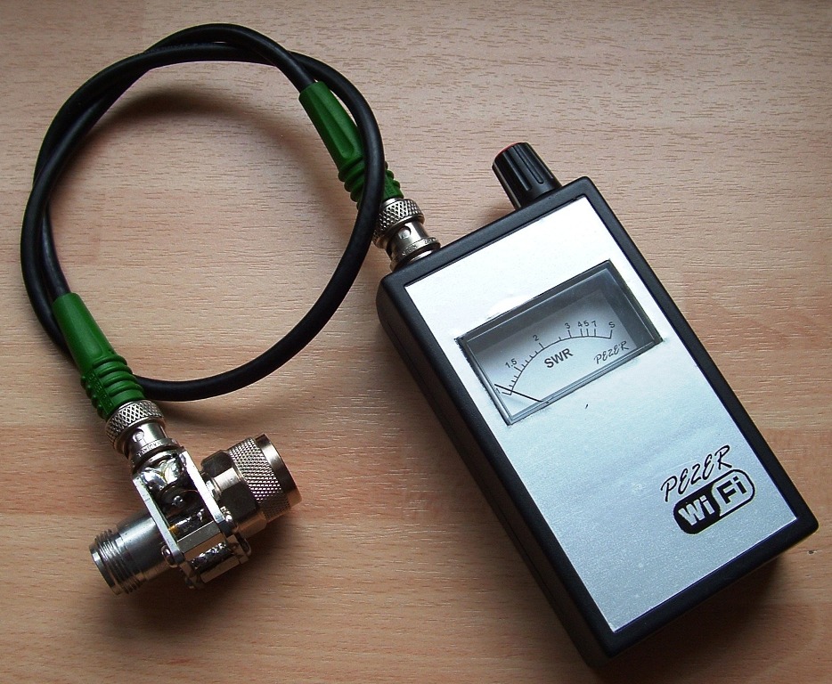
The device consists of two parts. One RF head
and a (preferably analog) indicator. An external SWR sensor is attached to the indicator with a BNC-BNC cable.
An Analog indicator is used to read the VSWR.
This meter has a Peak-Hold circuit with a 9 Volt
alkaline battery power supply. There is only one control to control the
power ON/OFF and meter Sensitivity. Meter sensitivity can be adjusted to
accommodate several RF sources, such as a Wifi Access Point, or VFO. |
Click on each image to enhance.
|
||||||||||||||||||||||||||||||||||||||||||||||||||||||||||||
|
This is the diagram for the RF Head. It is essential to use SMD size 0805 or smaller components and the PCB design below. Zx is the antenna port. “RF in” is connected to the Wifi Access Point (or other RF Generator) port. |
|
||||||||||||||||||||||||||||||||||||||||||||||||||||||||||||
|
This drawing shows the mechanical buildup of the external RF Head. Components
Components (SMD 0805): |
|
||||||||||||||||||||||||||||||||||||||||||||||||||||||||||||
|
|
|
||||||||||||||||||||||||||||||||||||||||||||||||||||||||||||
|
Use 10x25mm of Epoxy double sided PCB material.
You may either use an etching process or a
sharp hobby knife to cut out the copper pattern on the PCB. |
|
||||||||||||||||||||||||||||||||||||||||||||||||||||||||||||
|
Clear an area of copper behind the Zx port to minimise the capacitance of this port to ground. |
|
||||||||||||||||||||||||||||||||||||||||||||||||||||||||||||
|
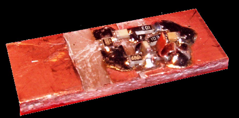
Mount the SMD Capacitors and resistors. Mount the diode last |
|
||||||||||||||||||||||||||||||||||||||||||||||||||||||||||||
|
The finished bridge |
|
||||||||||||||||||||||||||||||||||||||||||||||||||||||||||||
|
Assemble the RF Head using the PCB assembly, two flat N-Type bulkhead connectors, three metal 10mm long studs with M3 thread and six 7mm M3 machine screws. Solder the PCB in place. Make sure that it is not under mechanical stress. Solder the ground surface to the bulkhead connector at 4 places, making as much contact as possible. Solder the BNC to the assembly. The BNC is used to output the pulsed DC signal to the indicator. |
|
||||||||||||||||||||||||||||||||||||||||||||||||||||||||||||
|
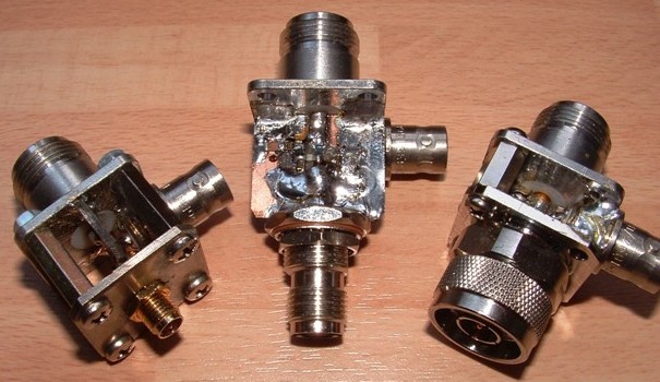
The photo shows three different versions of the bridge. RP-SMA, RP-TNC en N-Type antenna connector. |
|||||||||||||||||||||||||||||||||||||||||||||||||||||||||||||
|
Wifi hardware transmits in short bursts. You need a “peak-hold” circuit to convert the DC pulses from the RF head into a stable DC voltage for the indicating instrument. The design shown here is based on a quad OPAMP, TL084. OPAMP U1A creates a 'virtual ground' so that the OPAMP can be powered by a single 9 Volt battery. The voltage from the RF head consists of a pulsed DC signal (so no 2.4GHz present). The pulse width varies between 0.2-0.5ms with a repetition frequency equal to that of the SSID (beacon) interval set in the AP. Voltage is a few volts max and depends on the amount of unbalance in the bridge. The diagram shows a Peak-Hold/ Fast switch. This switch is not required and can be omitted. |
|
||||||||||||||||||||||||||||||||||||||||||||||||||||||||||||
|
Potentiometer SENSITIVITY is used to set the meter at full scale deflection
with a fully unbalanced bridge (short circuit plug attached to the Zx port).
The worst-case input VSWR of the bridge is 1:2, so you will NOT destroy your
Acces Point ;-) OPAMP U1B forms a peak-hold circuit wit the general purpose diode D1, C3 and R5. U1C and U1D buffer the output for the meter and a second (normally unused) output. Output to the meter is limited to +1.2/-0.6 Volt by means of three 1N4148 diodes. Switch S2 can bypass diode D1. With S2 closed, the OPAMP U1b acts as a unity gain buffer. The meter will react directly to changes in VSWR. This is beneficial when the VSWR meter is used with an amateur band radio. If the bridge is used exclusively on Wifi equipment, S2 can be omitted. OPAMP U1D provides an adjustable voltage to the - terminal of the meter. This allows compensation for leak-currents of D1 and offset voltage of the OPAMPs. |
|||||||||||||||||||||||||||||||||||||||||||||||||||||||||||||
|
|
|
||||||||||||||||||||||||||||||||||||||||||||||||||||||||||||
|
Homebrew 2.4GHz dummy load: |
 |
||||||||||||||||||||||||||||||||||||||||||||||||||||||||||||
|
Manufacture a scale for the analog indicator as shown
in the table below. You will be able to directly read the VSWR from the
meter. Download user manual (pdf, 450kB) |
||||||||||||||||||||||||||||||||||||||||||||||||||||||||||||
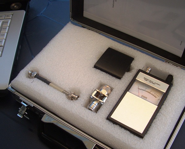
| For use in the field, I have constructed this custom case. It holds the VSWR Indicator, SWR head, BNC cable and a relative Field-strength sensor. |
 |
||||||||||||||||||||||||||||||||||||||||||||||||||||||||||||
|
Disclaimer I will not be responsible for damage to equipment, your ego, personal injury or worse that may result from the use of this material and material found on any links on my pages. You are responsible to make sure that your use any of my designs is legal in your country. |
|
|
|
Version: Nov-2008 |
|
|


 Copyright: Erwin Gijzen