6 GHz milli-Watt meter with DL5NEG Power sensor
This design utilises the diode power sensor designed by DL5NEG:
http://www.herbert-dingfelder.de/diodesensor/diodesensor.html
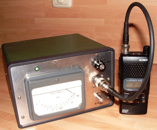
My GHz milli-Watt meter with analogue readout. Ranges: 10mW, 30mW, 100mW, 300mW and 1000mW

In contrast to AD8307 and the like designs, this design is very uncomplicated and straight forward. No doubt at the expense of some accuracy.
All parts are mounted on the front plate of the housing. And yes, the delicate indicator is held in place with sticky tape.
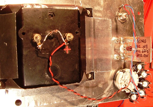
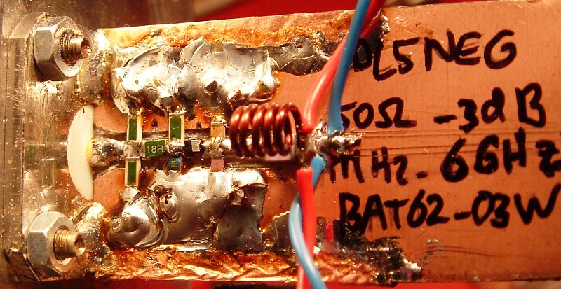
This is 'my' version of the DL5NEG Diode power sensor/ dummy load that can be seen here.
PCB size is reduced to N mounting flange size (25mm).
Contrary to DL5NEG's design, no vias were added to the PCB, but some Copper foil was soldered around both edges to connect front and back side PCB ground tracks as can be seen on the photograph above - This reduces the maximum useable frequency of the sensor, see note below. Ground track is soldered to the N-connector on both sides front and back. A Choke coil was added to help decouple RF for the lower frequencies. This Choke-coil (5 turns on 3mm) is shown as 'L' in Diagram.
Schematic diagram of the mW meter, including the DL5NEG Diode power sensor. Two Ge diodes in antiparallel are added across the indicator to protect it against surge voltages. You may wish to use Si diodes, depending on the maximum voltage on your indicator.
A BNC Socket is mounted on the front plate. It carries the DC signal from the RF detector. With the 6 position switch in EXT position, the detector is not loaded other than with the 270k resistor and Voltmeter impedance (>1M). I Use this position to get accurate and/ or relative measurements. The other positions select one of the five adjustable resistors, each set individually to get the corresponding readout on the indicator.
The DL5NEG power sensor is useable up to 6 GHz according to its designer (and who am I to argue). The highest frequency I have tested it on is 2.5GHz. In the 1000mW range Power dissipation in the 43 Ohm SMD resistor is higher than the design limit of ~100mW, but so far there seems to be no damage to it.
DL5NEG, the designer of this sensor contacted me, and requested me to add the following note:
"You mention that you are using metalized edges of the sensor board instead of vias. Well, metalized edges are always very good, but in that context I have found in extensive measurements that the vias directly around the diode are really important for a really flat frequency response. That is already relevant at 2.4GHz but especially at higher frequencies. So my statement that the sensor is good up to 6GHz is only valid if you really use these vias."
After receiving this comment, because I sometimes listen to good advice, I decided to retrofit the sensor with 8 vias. Here is a close-up of the modified sensor:
I Even managed not to break the diode in doing this :)
Disclaimer I will not be responsible for damage to equipment, your ego, personal injury or worse that may result from the use of this material and material found on any links on my pages. You are responsible to make sure that your use any of my designs is legal in your country. |
Copyright: Erwin Gijzen |
|
|
Version: Jan-2009 |
PE2ER.nl