Leader LDM-815 Dipmeter & LIM-870 Impedance meter
User Manual LDM-815 (1 MB Ms Word doc)
User manual LIM-870 (Special version, adapted to my modified Impedance Meter)
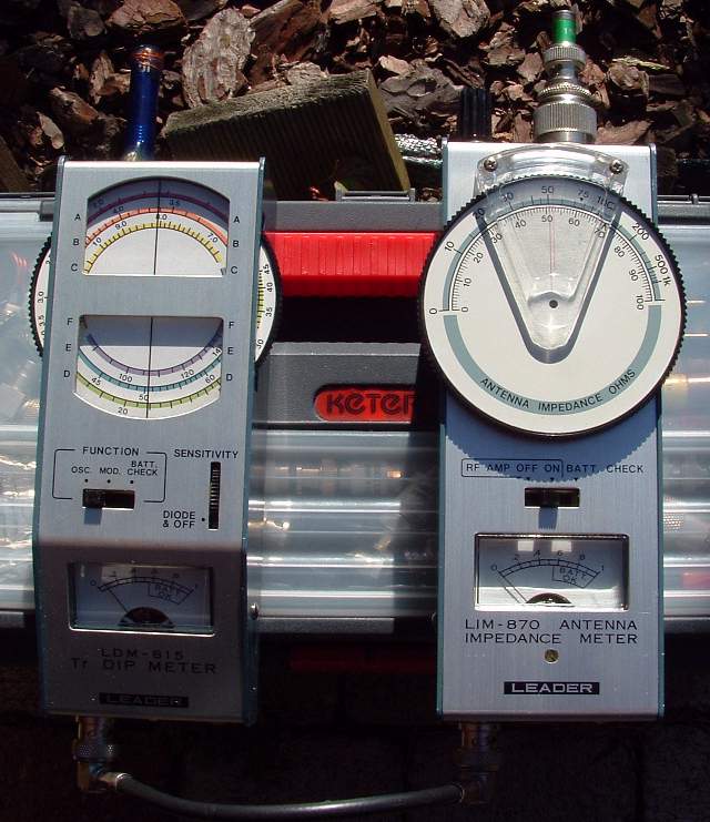
This page shows my Leader LDM-815 transistor dipmeter and Leader LDM-870 Impedance meter
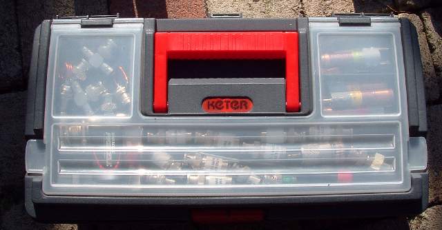
The ready to go case with coils, adapters and various dummy loads.
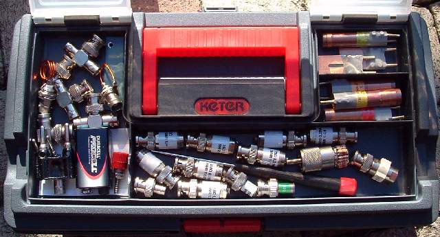
Photo: Inside the case, foam holds the dip and impedance meter in place.
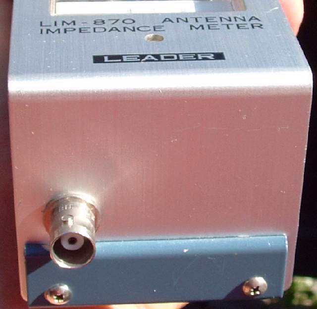
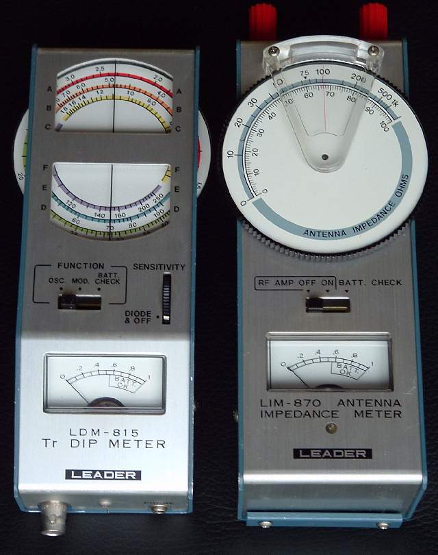
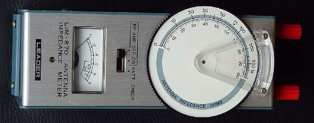
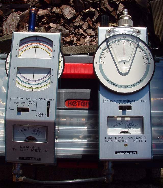
Photo: Front view of both units
The dipmeter and impedance meter can be screwed together to form an easy to handle unit.
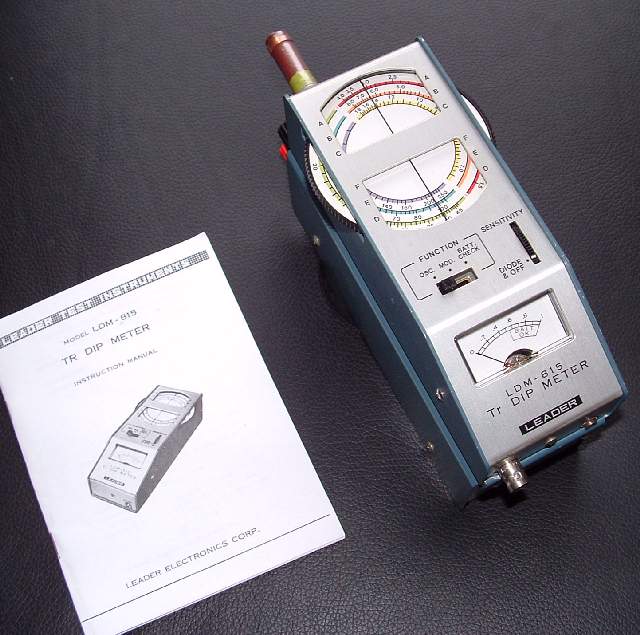
Photo: LDM-815 and LIM-870 Piggy-bagged together
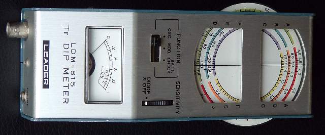
Photo: LDM-815 showing added RF OUT BNC
Diagram: LDM-815 Buffer amplifier
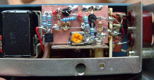
I Modified the LDM-815 to add an RF OUT BNC . This output can be used to drive a Frequency Counter or the LDM-870 Impedance meter.
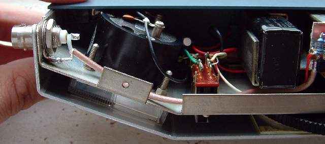
RF Is taken from the oscillator coil via a small capacitor. RF Is amplified by a High-Z BF981 and a BF199 amplifier. Both amplifier stages are only switched ON when a DC load of <10kΩ is attached to the BNC. A BC557 does the switching. The current drawn by the amplifier exceeds the normal dipmeter current by 10 times...
The LIM-870 normally accepts RF from the dipmeter via a pickup coil, connected to two Banana busses on the front of the meter.
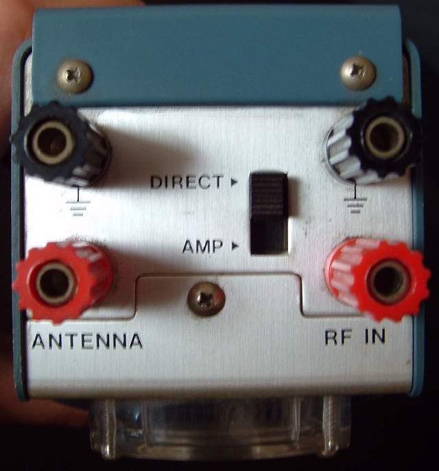
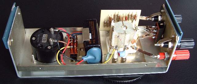
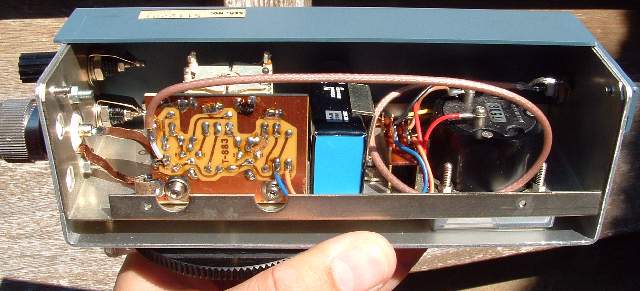
Photo: LIM-870 Inside view (before modification)
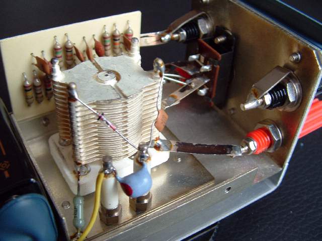
Photo: LIM-870 Close-up of the RF Bridge (before modification)
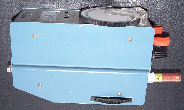
In order for the LIM-870 to accept RF Input from the BNC on the dipmeter, I added an RF IN BNC to the impedance meter.
In all systems I normally encounter, unbalanced coax is used to feed the antennas. So I decided to modify the bridge and add a SO-239 socket as Antenna connector. Two bananaplugs fascilitate measurement on balanced feed lines and connecting a ground wire.
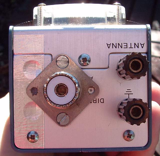
Inside, I hooked up the BNC RF input to the Amplifier input. It is no now longer possible to use the bridge without amplifier, I removed the switch...). The SO-238 ia connected to the variable capacitor with two strips of copper foil.
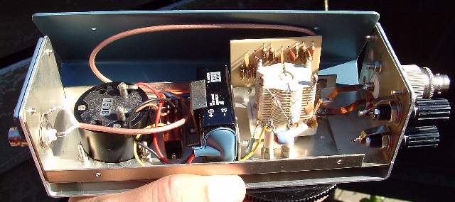
Photo: LIM-870 inside view from opposite angle.
Dip- and impedance meter connected together
A 50Ω dummy load is connected to the antenna port
The LIM-870 shows perfect balance with the dial set to the corresponding impedance.
Reliable impedance readings can be obtained below 100MHz only.
|
Disclaimer I will not be responsible for damage to equipment, your ego, personal injury or worse that may result from the use of this material and material found on any links on my pages. You are responsible to make sure that your use any of my designs is legal in your country. |
|
Copyright: Erwin Gijzen |
|
|
|
|
|
Version: Feb-2007 |
PE2ER.nl