
Antenna measurement using Leader LDM-815 Dipmeter
RF Impedance bridge
Although the RF dipmeter has largely been been replaced by instruments like spectrum analysers, RLC Bridges and SWR Analysers, the dipmeer still deserves its place in the amateur radio shack. For who can afford to spend hundreds of Euros on an SWR analyser that is only put to accosional use? This is the reason why RF Dip meters are 'hot' on eBay, and MFJ still carries a Dipmeter (MFJ-201) in its stock, right beside the SWR analysers.
Nevertheless, the use of an RF dipmeter is not always convenient or easy. For myself, I Always find it hard to determine the resonance frequency of an antenna using a dipmeter. It is hard to descern the shallow 'dip' at the resonance frequency both when measuring antennas and Ľ wave coax stubs. This is especially true at lower frequencies.
The traditional way of doing this measurement is to couple the dipmeter coil to the antenna or coaxial stub through a 1-3 winding link coil as shown below.
Antenna and transmission line measurement as shown in he dipmeter's user manual.
There is one big disadvantage to this method. The measurement result is the resonance frequency of the complete assembly of link-coil and antenna/ transmission line and not solely that of the device under test. This leads to noticeable errors at the higher (VHF) frequencies that can be as large as 10%.
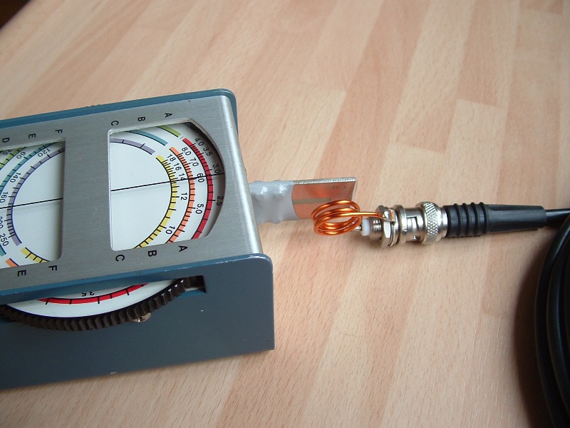
3 winding link coil – Large influence on measured frequency.
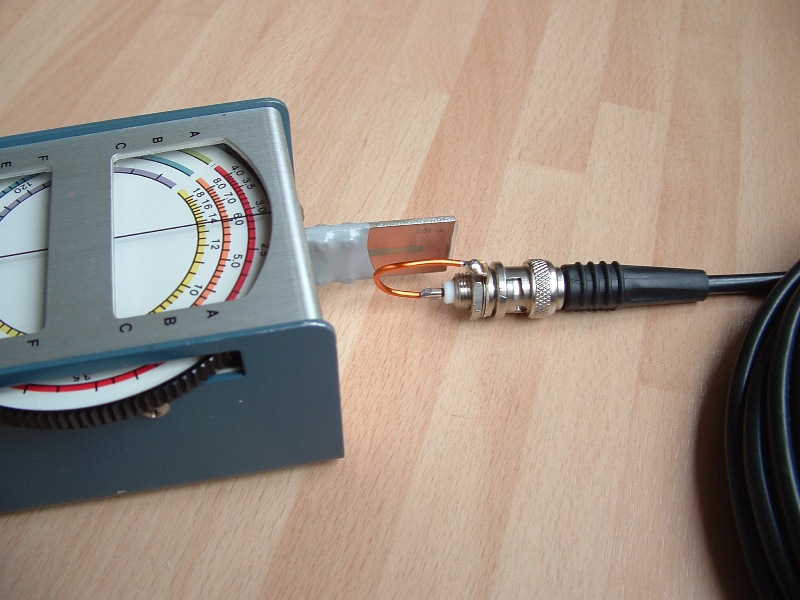
Single winding link coil – Very shallow ´dip´.
Transmission line measurement using link coil.
SWR Analysers as offered by MFJ and Autek utilise a measurement bridge with an adjustable RF generator. So I asked myself the question: 'Would it be possible to drive an RF bridge using a dipmeter?'
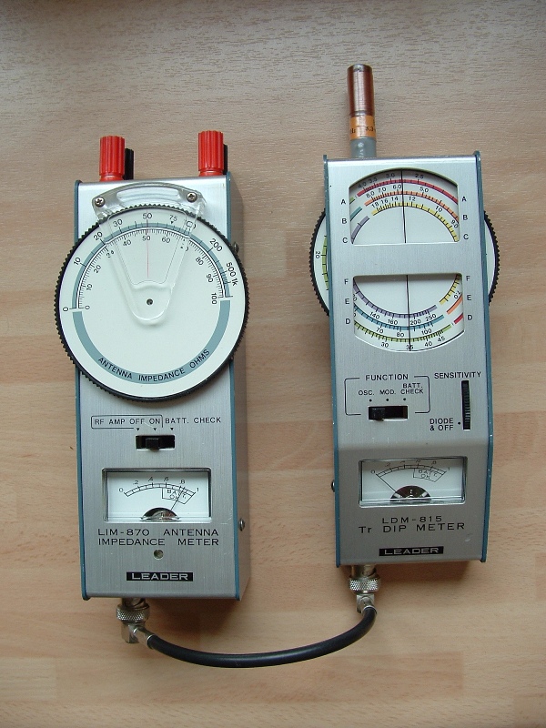
Leader LIM-870 impedancemeter and LDM-815 dipmeter.
The answer is'Yes'. To be honest, I am not the first person to think of this solution. In fact, there used to be an instrument on the market that complements my RF dipmeter; the Leader LIM-870 impedance bridge. This RF bridge determines the RF Impedance of a random load (Zx) at a specific frequency (set by the dipmeter). Or you can set the impedance bridge to a certain impedance (Like 50 or 600 Ohms) and vary frequency to determine the frequency at which the load resembles the set Impedance. It is essentially a Wheatstone bridge, using a variale capacitor in both arms of the bridge. The needle instruments shows the unbalance of the bridge. The Dipmeter is used to excite the RF bridge. The Device Under Test (DUT) is attached to the terminals at the front face of the unit. Unfortunately, the 'dip' found is usually very broad, especially in the higher region (100-150 MHz). Therefore, you can only determine the impedance by approximation. Once you have determined the load impedance, you can calculate the Voltage Standing Wave (VSWR) ratio the load would present to a given system.

Rhe RF bridge inside the LIM-870.
There is another disadvantage to this device: It is even harder to obtain one than it is to obtain a dipmeter. This makes homebrewing a bridge an attractive alternative.
Copying the LIM-870 is difficult, despite its simple design. This is mostly due to the use of a special variable capacitor. It consists of a rotor and two stators. In centre position, capacitance between the rotor and each of the two stators is equal. By rotating the rotor, capacitance to one stator increases, while capacitance to the other stator decreases. Because of this, and the degrading performance of the LIM-870 above 100 MHz, I decided against copying the LIM-870 design.
Modern SWR Analysers utilise a resistive RF bridge and some electronics to convert the measured voltages to VSWR and impedance. The variable capacitor from the LIM-870 bridge is replaced by fixed resistors. Analysers like the ones manufactured by Autek en MFJ, a 50 Ohm brug is used (drawn in blue in the diagram below). In order to calculate the properties of Zx, 3 electrical voltages are measured. U1 (the green circuit) is attached to the fixed arm of the bridge. U2 (in red) is a measure for the bridge unbalance and hence the ratio between Zx and the 50Ω reference. Using only U1 and U2, it is no possible to determine if Zx is greater or smaller than the reference. Therefore, a third voltage must be detected: U3 (In yellow) is a measure for the absolute value of Zx. VSWR and (complex0 impedance can be calculated from U1, U2 and U3. The only thing that can not bedetermined is the sign of the coplex part of Zx. Is Zx capacitive or inductive? That has to be determined by varying the measurement frequency. If Zx increases with frequency, Zx is likely Inductive. If Zx decreases with frequency, Zx is capacitive. This is mostly true for antennas around the frequency of resonance, but keep in mind that there are exemptions.
As said, the most commonly used bridge is designed for 50 Ohm antenna system. Using the power of electronics, this bridge can olso be used in other systems, for example 300 Ohm.
The RF bridge from a modern SWR analyser.
If you don't need to calculate the complex impedance of Zx, a simpler bridge can be used. I Only want to know antenna SWR and use only the RF Bridge (blue) and U2 (red) part of the circuit.
There are some advantages of using this simplified bridge instead of the LIM-870 circuit. The 'dip' is deeper and easier to determine and the direct coupling of the bridge eliminated the influence of the link cil on the measurement.
Of course, there are some drawbacks. Not incorporating the U1 detector means that the bridge must be calibrated each time you change the measurement frequency and there is some influence of the load impedance on the excitation voltage (and hence on the indicated SWR). Also, not using U3 means that there is no information on the absolute value of Zx.
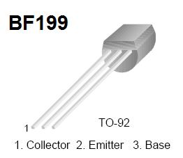
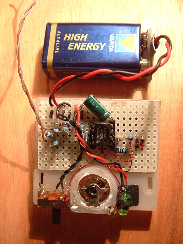
I Use my dipmeter as an RF generator. It has an RF-Out connector on it. This output is not commonly found on dipmeters, but it can be added to an existing dipmeter. One design has been published in the RAM (Radio Amateur magazine), but I would like to introduce a different design. It is somewhat more complicated but it has the advantage of an automatic 'energy saving' mode. The RF buffer consists of a high impedance dual gate MOSFET that keeps the loading of the dipmeter coil to a minimum. The first stage is followed by a Bipolar transistor driver circuit. Output power still is only a few milliwatts. This is more than sufficient to drive the Impedance Bridge described on this page. The 50k varable resistor is adjusted to produce the largest possible RF voltage with acceptable distortion. The 27k resistor was selected to set the collector voltage of the BF-199 approximately to half that of the supply voltage. You may need to change the value of this resistor, as it depends on the individual transistor parameters which value is needed.
The current drawn from the battery by the dipmeter is only about 1mA. The RF Amplifier however draws up to 10 times as much! Therefore I added a small circuit that enables the RF amplifier only when something is connected to the RF OUT connector. If the output is not in use, the RF Amplifier is switched off, saving the internal battery. This task is accomplished by a single BC-557 transistor and some resistors.
Dipmeter RF Output buffer.

Buffer in my LDM-815
NOTE: The transistor used in this amplifier differs from the BF199. BF199 Connections are as follows:
The RF Bridge consists of three tal 50 Ohm resistors and an antenna connector (BNC). The bridge is in balance when the Zx port is terminated in a 50 ohm load. T In that case, the voltage on the node R1/R2 is equal in both magnitude and phase to that on the node R3/Zx. The detector between thes two nodes (D1), will produce 0 Volt (DC). An any other valy of Zx, te bridge detector output will be some value other than 0V. In my bridge, the 50 Ohm resistors are formed by parallelling two 100 Ohm 1% SMD resistors.
RF Impedantie bridge circuit
TL082 (Dual OPAMP)
For the detecor, I use a Germanium point contact diode AA116. Althought the RF voltage on this diode remains well below the Forward Voltage of this diode (~200mV), the detector will prouce a useable DC voltage! It is operated in the non-linear area of the semiconductor around the 0 Volt. In this application, the humble Ge diode outperforms modern Shottky diodes.
The DC voltage for maximum inbalance in the bridge lies in the order of 50 millivolt (Zx is open or shorted) but can not be loaded. An OPAMP TL-082 buffers the detector voltage and amplifies it enough to drive a 300mV VU meter (A = 7,8x). The TL-082 houses two OPAMPs. One OPAMP is used to establish a 'Virtual Ground' at exactly half the supply voltage. Th other OPAMP is used as non-inverting DC amplifier. Amplification "A" is determined by the ratio of two resistors; A = 1 + (R7/R6).
The bridge unbalance is a measure for the VSWR. So it is possible to draw a scale calibrated in VSWR on the needel indicator. The indicated valua is most reliable for values below SWR 1:2.0. SWR Values above 1:3.0 Are to be consiedered as a coarse indication of the actual value. The relatively high output impedance of the RF Amplifier and the design of the circuit make readouts above 1:3.0 unreliable. The graphic below shows the indicated VSWR versus the theoretical SWR (SWR Ref) as a function of a real Zx, at a frequency of 10 MHz.
Indicated SWR at different values for Zx.
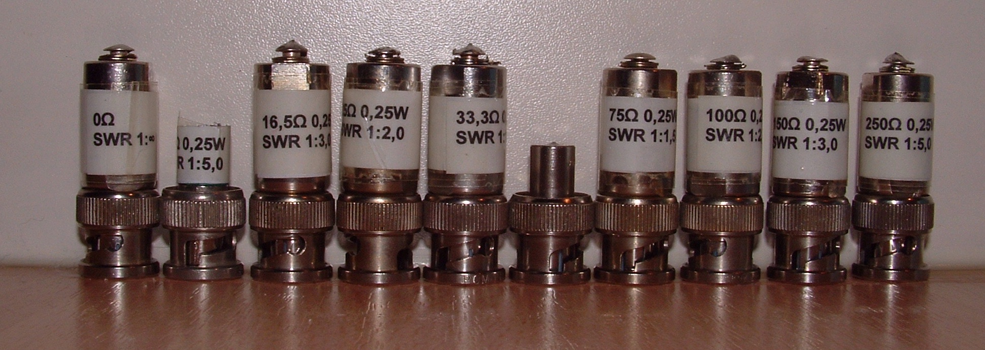
Terminators used for the test.
The DC Amplifier built around the TL082 dual OPAMP can be placed on a small piece of vero board. The limited amount of parts makes it convenient to use this building method. The circuit board is placed behind the indicator scale. Place the decoupling capacitor as close to the OPAMP as possible.The further layout is not critical.
DC Amplifier board behind VU meter.
Test the circuit by applying the 9V DC Power supply. The VU meter should barely move, when no RF signal is fed to the amplifier. At a DC voltage approximately 40 mV, the VU meter should defect fully. If this is not the case, adjust the Amplification of the DC Amplifier.
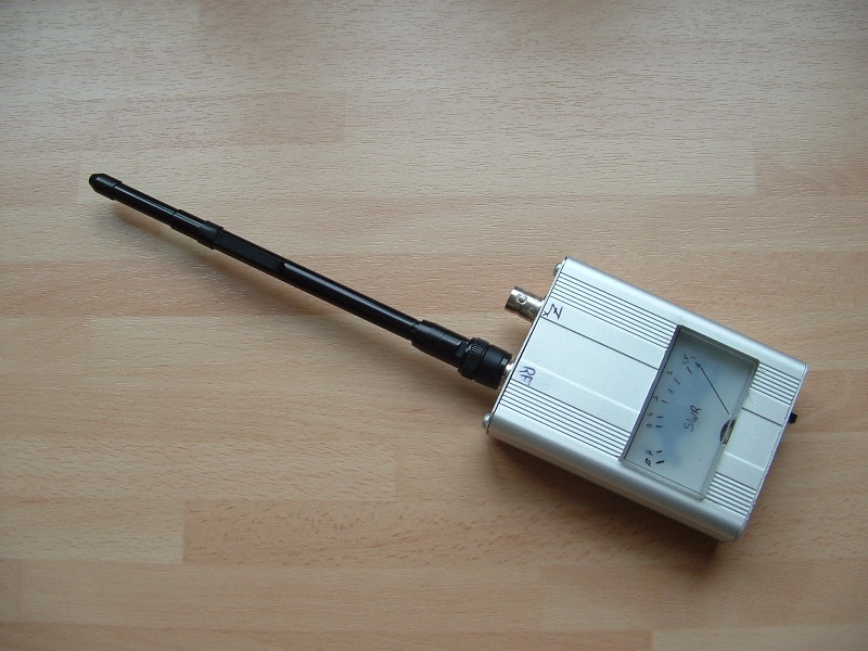
The amplifier board, VU meter, 9 Volt Alkaline battery and RF bridge fit snugly ito a 25 x 65 x 90mm housing. The case used in the prototype is a salvaged housing made from aluminium, but of course a new housing from the same material, other metal or PCB material will also do well.
The RF Bridge is built around two BNC Chassis mounted sockets. They are attached first to the housing front place. The spacing between the two sockets on the prototype is 25mm, but this is not a critical measurement. Remove any unwanted Teflon from the BNCs and shorten the center pin to approximately 3mm. The RF Bridge will be placed on a piece of double-sided Epoxy PCB, measuring 15x40x1.5mm. Cut the PCB to fit between the BNCs and cut the pattern on the PCB using a sharp Exactor knife. Start with cutting a 3mm track between the two center contacts. this will form a 50 Ohm stripline. As the dimension of the bridge is small in reference to the minimum wavelength, the dimension of the stripline is not very critical.
Now solder the PCB to the BNC connectors. Make sure to
solder the ground to both the upper and underside of the PCB.
The rest of the circuit board pattern is cut as we move along installing the components. For the bridge, I use SMD type components for their excellent RF properties at the VHF and even UHF range. As shown, the bridge will function to frequencies up to 500MHz. First, join the upper and lower part of the circuit board using a thin copper foil at each short side. Break the 3mm strip line close to the right hand BNC socket. Place two 100 Ohm SMD resistors in parallel across the gap. Together they will form R3 of the RF Bridge. Cut a strip right next to the 50 Ohm strip line. This will be the node R1/R2. R1, R2 and R3 are all formed by placing two 100 Ohm resistors in parallel. For R1 and R3, the two resistors are positioned side by side.
For R2, the resistors are stacked on top of each other to save room. R2 is the reference resistor that Zx is compared to, so it is wise to make sure that the resistor has a good path to the RF ground. This is the reason for me to add another piece of copper foil that links the ground track at to component side of the PCB to the ground track at the lower side. Cut out the 3 remaining islands on the circuit board and install the two 470p capacitors, two 10k Ohm resistors and the 1n capacitor.
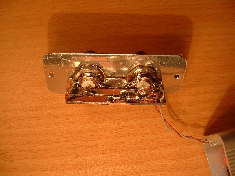
The Germanium diode is a standard leaded component and
is mounted floating above the circuit board. Be careful when bending the leads
on the diode; the glass housing is prone to cracking.
PCB and component layout.
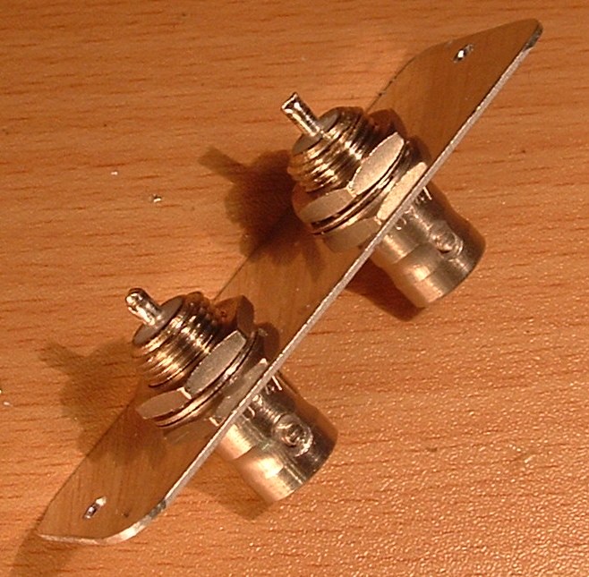
Two BNC jacks on the front plate.
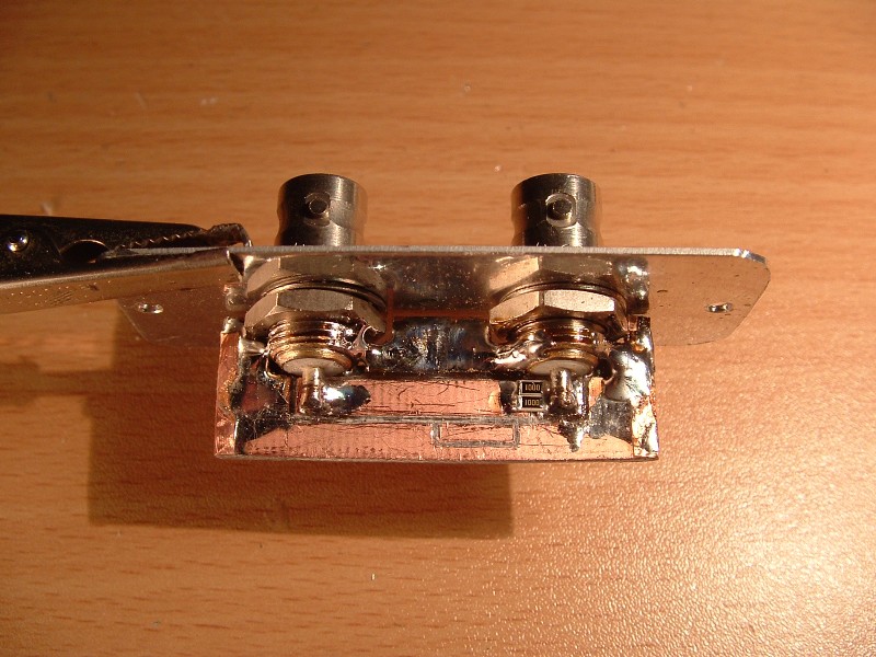
RF Impedance bridge. Start with placing R3.
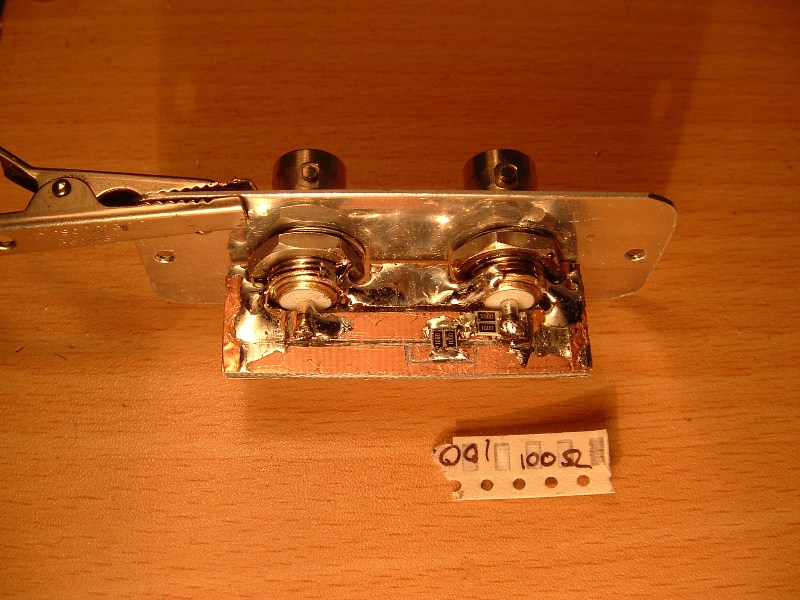
R1 also finds its place.
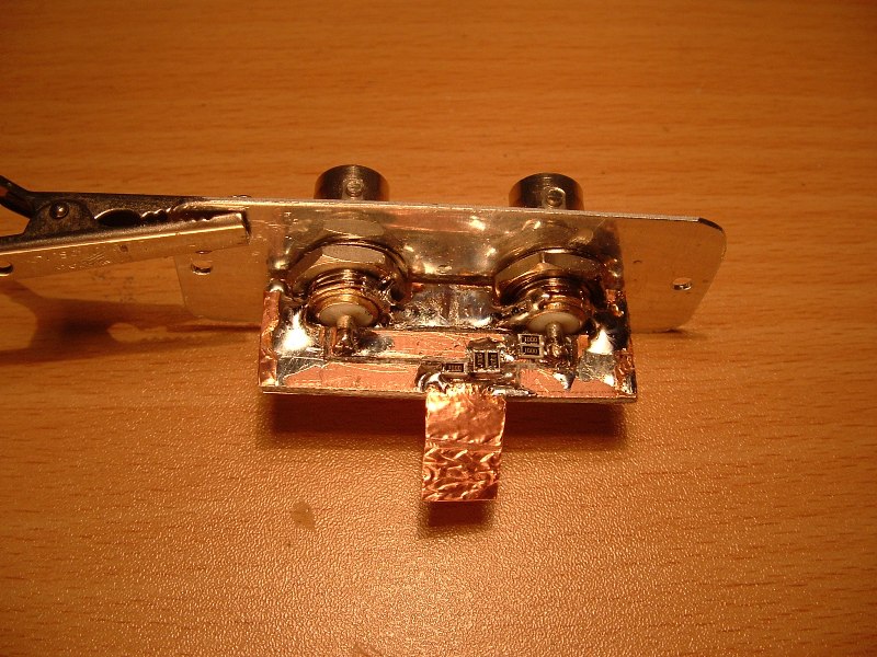
R2 Is the reference for Zx. Make sure it is connected to ground properly (I use a piece of copper foil to connect it to the ground on the other side of the circuit board).
The two 470p capacitors (pink, no markings).
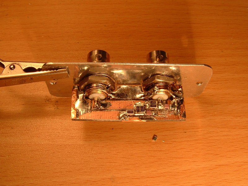
The completed RF Bridge
Next, make a scale for the SWR meter.
|
Indication |
SWR 1:x |
|
0,00 |
1.0 |
|
0,2 |
1.5 (SET) |
|
0,333 |
2.0 |
|
0,5 |
3.0 |
|
0,6 |
4.0 |
|
0,667 |
5.0 |
|
1,00 |
∞ |
In the table an indication of 1,00 represents full deflection of the VU meter, and 0,00 is the resting position of the needle. The electrical offset of the OPAMP may cause the resting position of the meter to differ slightly from the mechanical resting position.
With your new device, you can now accomplish the following:
· Determine the operating frequency of an antenna.
· Determine the VSWR of an antenna (system).
· Determine transmission Line resonance frequency.
· Determine transmission Line velocity factor
· Determine Relative Field Strength
When poerforming measurements on antenna systems, take into account the possible effect of other (transmitting) antennas in the neighbourhood of the Antenne under test. Energy received from other antennas will upset your measurement, as is the case with most SWR analysers using broadband detectors.
|
Disclaimer I will not be responsible for damage to equipment, your ego, personal injury or worse that may result from the use of this material and material found on any links on my pages. You are responsible to make sure that your use any of my designs is legal in your country. |
|
Copyright: Erwin Gijzen |
|
|
|
|
|
Version: Sep-2011 |
PE2ER.nl