Phone line interface (common ground)
Description of the design
On this page, you will find the design for a phone line interface. This interface will allow you to use a headset/ boom microphone combination (boomset) as a telephone. The design is intended to answer incoming calls or take over a call started from another telephone on the same line. It is intended to be placed in parallel to an existing telephone unit, a DTMF or ring tone generator are not included. The boomset can be used to comfortably conduct a lengthy handsfree conversation. The circuit utilises the line voltage and requires no external power supply. I have only tested this design on the Dutch phone line system and can not guarantee that it will work on any other system.
To complete this design to a DTMF Dialler can be added. The DTMF signal of for example a phone-answering-machine remote control can be mixed with the microphone signal so you can dial out.
Use of this circuit on the Dutch KPN telephone network is possible, but not allowed. It can be used legally on an internal company network.
Circuit
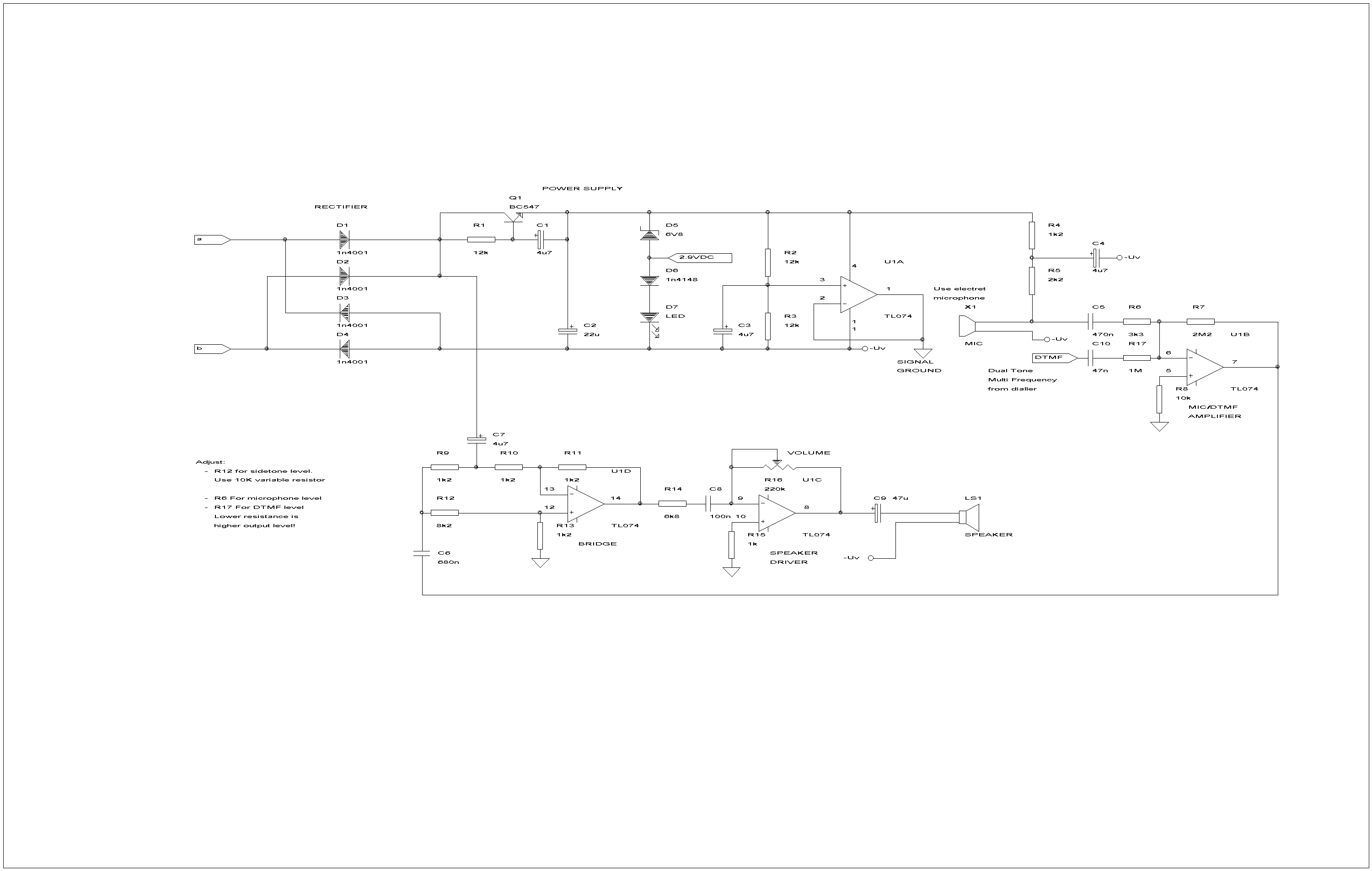
The circuit is based around a quad OPAMP U1 like the TL074 or TL084, on a piece of vero board. The line voltage (a,b) is rectified with a rectifier bridge. A Gyrator separates the DC from the voice signal. A Zener diode, diode and a Light Emitting Diode form a shunt voltage regulator. The diode and the LED make it possible to supply 2,2 volt to the tone dialler (DTMF Generator). As a bonus, the LED will illuminate as the interface is connected to the network and can be used as a off-hook indicator.
U1A generates a virtual ground for the other 3 OPAMPS. U1B Amplifies the microphone signal and adds in the DTMF signal. U1C Amplifies the line signal to the right level for the headset. The volume control is not a luxury! When you use this design, you will soon notice that the sound level of incoming calls is far from constant. U1D forms a bridge to separate the Rx and Tx signal and has an impedance of approximately 600 Ohm.
Power for the electret capacitor microphone comes from the circuit. The speaker as drawn consists of the two headset speakers connected in series to raise the impedance of 30 Ohm speakers, or in parallel to raise the sound level in 300 Ohm speakers.
Not drawn here is the hook-switch. This DPST switch is mounted in line with the a and b line.
Adjustment
R12 is used to balance the bridge to minimise the feedback of the microphone signal to the speaker. By varying the value of R6, it is possible to customise the interface to the specific microphone. R17 can be tweaked to adjust the tone dialler signal level.
Hum
On the prototype, there was an annoying 100Hz hum audible. The solution to this problem, was to place a grounded sheet af aluminium tape under the PCB (which is mounted in a plastic case). Isolate the tape from the circuit with PVC tape or cardboard.
Transferring a call
Transferring a call can be done 'the old fashioned way' by shorting the a line shortly to ground or by opening the Hook-switch for < 0.1 seconds, depending or your switchboard.
|
Disclaimer I will not be responsible for damage to equipment, your ego, personal injury or worse that may result from the use of this material and material found on any links on my pages. You are responsible to make sure that your use any of my designs is legal in your country. |
|
|
|
Version: 3-feb-2002 |